Tensor Format Conversions#
Overview#
Deploying neural networks on AMD NPUs requires transforming tensor data from standard CPU formats into NPU-specific formats. CPU-side frameworks such as PyTorch, TensorFlow, and ONNX Runtime store tensors in NCHW or NHWC format, which organize data in a row-by-row layout. AMD NPUs instead use HCWNC4 and HCWNC8 formats, which group pixel channels into fixed-size blocks of 4 or 8 channels. This blocking allows the NPU to load and process multiple channels in a single memory transaction, matching the hardware’s internal vector width.
The responsibility for format conversion depends on which runtime you are using. ONNX Runtime applications rely on the Vitis AI Execution Provider to handle conversion automatically—input data is transformed from CPU format to NPU format before inference, and results are converted back afterward. VART Runtime applications must implement format conversion manually, transforming input tensors before submission to the NPU and converting output tensors back to CPU format after execution completes. ONNX Runtime users can also implement manual conversion to reduce per-inference latency.
Incorrect data alignment degrades NPU performance. When tensor data does not match the expected NPU format, the NPU must perform additional operations to reorganize data before processing can begin. This increases memory bandwidth consumption and reduces throughput as processing units wait for data to arrive in the correct layout.
This section describes the memory layout of each format, explains how to read format requirements from the compiler’s output, and covers the dimensional transformations required when implementing manual conversions.
For VART-X pipelines that connect hardware preprocess to NPU inference, the NPU Format Selection Guide walks through mapping compiled-model input tensor metadata to preprocess-config.colour-format (using ml_vart --get-model-info). See also VART Application Development (Mapping between Tensor Layout and Colour Format).
Memory Layout Formats#
The following sections describe the memory layout formats used by the CPU and NPU respectively, including their structure, memory organization, and characteristics.
CPU Data Formats#
CPU frameworks typically represent tensor data in one of two standard formats: NCHW and NHWC. Both are row-major layouts that differ in the order in which the channel and spatial dimensions are traversed.
NCHW (Batch-Channel-Height-Width)#
NCHW is a planar memory layout in which each channel occupies a complete and contiguous 2D spatial plane in memory. All spatial values for one channel are stored before any values for the next channel.
The logical structure of NCHW is defined as:
[N, C, H, W]
where:
N - Batch size: the number of independent samples in the batch.
C - Channels: the number of feature channels per sample.
H - Height: the number of rows in each spatial plane.
W - Width: the number of columns in each spatial plane.
Note
These dimension labels apply specifically to 4D tensors used in spatial processing operations such as convolution. For other operations or tensor ranks, the letters serve as positional identifiers for dimensions 0, 1, 2, and 3 respectively.
Memory Layout
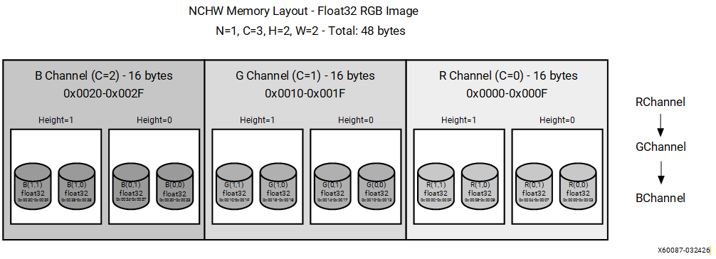
For an RGB image with dimensions (N=1, C=3, H=2, W=2), data is stored in the following order:
[R00, R01, R10, R11, G00, G01, G10, G11, B00, B01, B10, B11]
All red channel values are stored first, followed by all green channel values, then all blue channel values. Within each channel plane, values are stored in row-major order. This layout is efficient for channel-wise operations such as batch normalization and channel scaling because all values for a given channel are contiguous in memory. Spatial operations that access multiple channels at the same pixel location require strided memory access.
NHWC (Batch-Height-Width-Channel)#
NHWC is an interleaved memory layout in which all channel values for a given spatial location are stored contiguously. The channel dimension is the innermost (fastest-varying) dimension in memory.
The logical structure of NHWC is defined as:
[N, H, W, C]
where N, H, W, and C carry the same meanings as defined for NCHW above.
Memory Layout
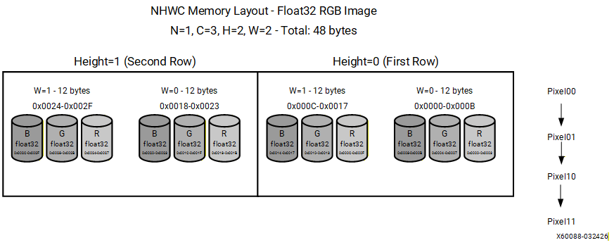
For an RGB image with dimensions (N=1, H=2, W=2, C=3), data is stored in the following order:
[R00, G00, B00, R01, G01, B01, R10, G10, B10, R11, G11, B11]
All channel values for the top-left pixel are stored first, followed by all channel values for the next pixel, proceeding in row-major spatial order. This layout is efficient for pixel-wise operations such as activation functions because all channel values for a given spatial location are contiguous in memory. NHWC is widely adopted by mobile and edge inference frameworks, including TensorFlow Lite and select ONNX Runtime execution providers.
NPU Data Formats#
Overview#
HCWNC4 and HCWNC8 are channel-blocked memory layouts optimized for NPU processing. They group pixel channels into fixed blocks (4 or 8) to enable efficient aligned memory transactions and vectorized operations.
Key benefits include:
Channel locality: Contiguous storage of pixel channels.
Vectorization support: SIMD-friendly for loading/storing multiple channels.
Alignment: Predictable memory block sizes (padding as needed).
Memory Layout Structure#
Dimension Definitions
Dimension |
Description |
|---|---|
H |
Height (rows) |
W |
Width (columns) |
N |
Batch size |
C |
Channel |
C_x |
Channel block size (4 or 8) |
HCWNC4 (Height-Channel-Width-Batch-Channel4)#
HCWNC4 is a channel-blocked memory layout format that organizes tensor data by grouping channels into fixed-size blocks of 4.
The logical structure of HCWNC4 is defined as:
[H, C/4, W, N, 4]
Data is traversed from the outermost dimension (H) to the innermost (4 channels per block). The channel dimension is subdivided into blocks of 4. If the total channel count is not divisible by 4, the final block is zero-padded to maintain uniform block sizes throughout memory.
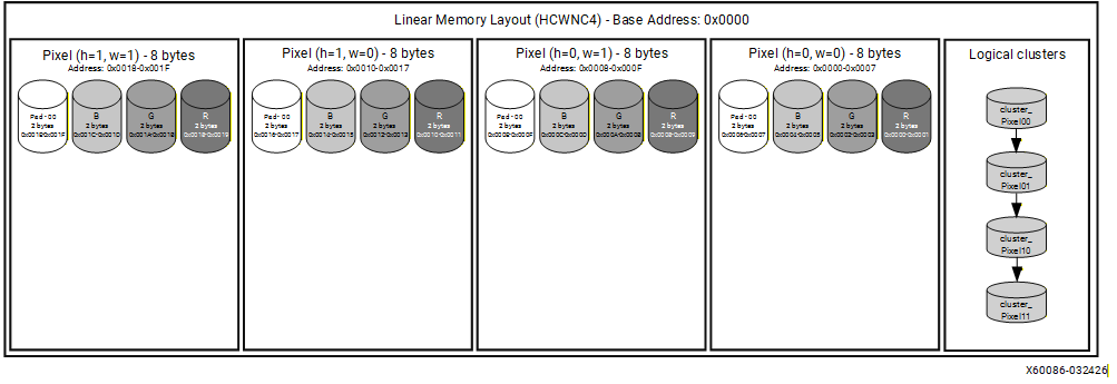
Example 1: RGB image (N=1, H=2, W=2, C=3)
An RGB image has 3 channels, which is not divisible by 4. To satisfy the HCWNC4 format requirement, the channel dimension must be padded with one zero value to form a single complete block of 4:
Original channels : [R, G, B]
After padding : [R, G, B, 0]
Since this example uses a batch size of 1 (N=1), and all three channels fit within a single block, the memory layout is straightforward. For each spatial position (h, w), one 4-element entry is stored containing the R, G, and B values followed by a zero-padding element.
Note
In VART Runner::execute(), the N slot in HCWNC4 HW metadata stays 1 for each buffer; device batching is expressed as multiple NpuTensor objects (one per frame), not as N > 1 inside a single HW shape. See Batch buffers and HCWNC4.
Memory layout:
H |
W |
Values Written to Memory |
|---|---|---|
0 |
0 |
R[0,0], G[0,0], B[0,0], 0 |
0 |
1 |
R[0,1], G[0,1], B[0,1], 0 |
1 |
0 |
R[1,0], G[1,0], B[1,0], 0 |
1 |
1 |
R[1,1], G[1,1], B[1,1], 0 |
The figure below illustrates the memory layout of a BF16 RGB image (H=2, W=2, C=3) in HCWNC4 format. Each pixel occupies 8 bytes, corresponding to four BF16 values: R, G, B, and one zero-padding element:
Channels per entry: [R, G, B, Zero_Padding] – 8 bytes per pixel (BF16)
HCWNC8 (Height-Channel-Width-Batch-Channel8)#
HCWNC8 is a channel-blocked memory layout format that organizes tensor data by grouping channels into fixed-size blocks of 8.
The logical structure of HCWNC8 is defined as:
[H, C/8, W, N, 8]
Data is traversed from the outermost dimension (H) to the innermost (8 channels per block). If the total channel count is not divisible by 8, the final block is zero-padded to maintain uniform block sizes throughout memory.
Example: 8-Channel Feature Map (N=1, H=2, W=2, C=8)
When the channel count is exactly 8, no padding is required and the data fits into a single complete channel block. Each memory entry contains all 8 channel values for a specific combination of height, channel block, and width.
The traversal follows this sequence:
for each H              (H = 0, 1)
    for each Channel Block  (Block 0 only)
        for each W      (W = 0, 1)
            for each N  (N = 0, fixed at batch size 1)
                write 8 channel values
This produces 4 memory entries in total:
2 (H) x 1 (Channel Block) x 2 (W) x 1 (N) = 4 entries, each containing 8 values
The table below summarizes the memory layout. Each row represents one channel block at a given height. The stored values follow the same pattern across all width positions. The notation C[h,w] denotes the value of channel C at height h and width w.
H |
Channel Block |
Values Stored (for each W = 0, 1) |
|---|---|---|
0 |
Block 0 (C0-C7) |
C0[0,w], C1[0,w], C2[0,w], C3[0,w], C4[0,w], C5[0,w], C6[0,w], C7[0,w] |
1 |
Block 0 (C0-C7) |
C0[1,w], C1[1,w], C2[1,w], C3[1,w], C4[1,w], C5[1,w], C6[1,w], C7[1,w] |
AB Format#
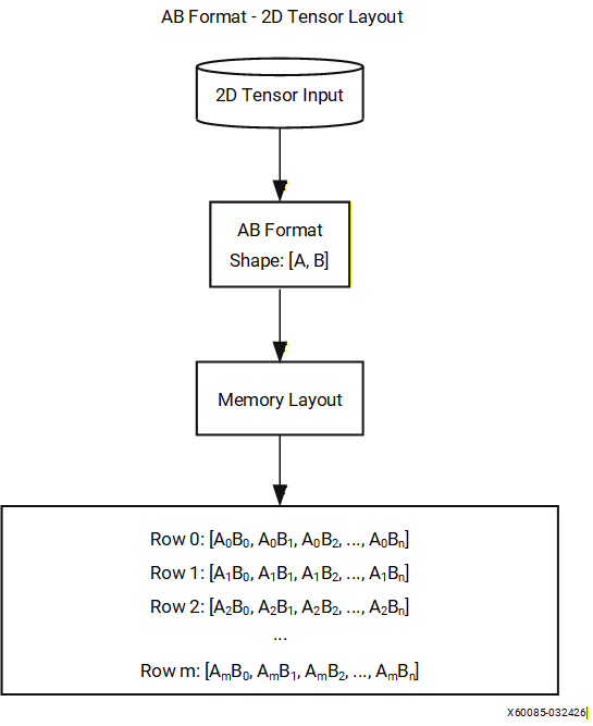
The AB format is a standard row-major memory layout for 2D tensors, where A represents the outer (row) dimension and B represents the inner (column) dimension.
The logical structure is defined as:
[A, B]
This format is used for 2D output tensors produced by fully connected and classification layers. Common use cases include classification layer outputs (A = batch size, B = number of classes) and dense layer outputs (A = batch size, B = number of features).
Data is stored in row-major order with the B index varying fastest. Each row corresponds to a fixed value of A, and rows are stored consecutively in memory:
Row 0: (0,0), (0,1), (0,2), ..., (0,B-1)
Row 1: (1,0), (1,1), (1,2), ..., (1,B-1)
...
Format Comparison#
The table below summarizes the key characteristics of each supported memory layout format. Selecting the appropriate format depends on the target hardware, the nature of the compute operations, and the channel width of the tensor.
Aspect |
NCHW |
NHWC |
HCWNC4 |
HCWNC8 |
|---|---|---|---|---|
Channel Organization |
Planar: all spatial data for one channel is stored before the next |
Interleaved: all channel values for one pixel are stored together |
Channel data grouped into consecutive blocks of 4 |
Channel data grouped into consecutive blocks of 8 |
Memory Access Pattern |
Efficient for operations that iterate over channels independently |
Efficient for operations that iterate over spatial locations |
Optimized for 4-wide vector loads and stores on the NPU |
Optimized for 8-wide vector loads and stores on the NPU |
Best Use Case |
Convolution-heavy workloads on CPU and GPU |
Mobile and edge inference workloads |
NPU workloads with 4-wide SIMD vector processing units |
NPU workloads with 8-wide SIMD vector processing units |
Cache Efficiency |
Favorable for channel-wise operations such as batch normalization |
Favorable for pixel-wise operations such as activation functions |
Optimized for NPU local memory access patterns |
Optimized for NPU local memory access patterns |
When targeting the NPU, HCWNC4 and HCWNC8 are the preferred formats as they align channel data with the NPU vector processing width, reducing the number of memory transactions and improving overall throughput. NCHW and NHWC are more commonly used when targeting CPU or GPU execution providers, where their respective access patterns offer better cache utilization.
Compilation Report#
When the Vitis AI compiler processes an ONNX model, it generates a flexmlrt-hsi.json file that describes the input and output tensor configurations required for NPU deployment. This file defines how tensor data is represented on the CPU side and how it must be reformatted for efficient execution on the NPU hardware.
For compile-time flags that let VART supply quantization and dequantization parameters to preprocess and postprocess blocks (so manual scale factors in application JSON can be omitted), see Quantization Parameters for VART Applications.
File Location#
The compilation report is written to the following path:
<CACHE_DIR>/<CACHE_KEY>/vaiml_par_0/0/flexmlrt-hsi.json
File Structure#
The JSON file contains two top-level arrays, inputs and outputs, each describing the tensor format transformation required at the CPU-NPU boundary. For each tensor, the file specifies both the CPU-side representation and the corresponding NPU hardware format.
Each tensor entry contains the following fields:
Field |
Required |
Description |
|---|---|---|
name |
No |
Compiler-generated identifier for the NPU buffer (for example, |
tensor_name |
No |
Logical name of the tensor, matching the corresponding ONNX tensor name. |
cpu_shape |
Yes |
Shape of the tensor as seen by the CPU, expressed in the order defined by cpu_format. Must match the ONNX model shape. |
cpu_format |
Yes* |
Memory layout format used on the CPU side (for example, NCHW or NHWC). *Not required when rt_transformations fully specifies the layout. |
cpu_dtype |
Yes |
Data type of the tensor on the CPU side. Supported values: fp32, fp16, bf16, int8, uint8. |
hw_shape |
Yes |
Shape of the tensor as required by the NPU hardware, expressed in the order defined by hw_format. |
hw_format |
Yes* |
Memory layout format required by the NPU hardware (for example, HCWNC4 or HCWNC8). *Not required when rt_transformations fully specifies the layout. |
hw_dtype |
Yes |
Data type of the tensor on the NPU hardware side. |
scale_factor |
Conditional |
Quantization scale used when converting between cpu_dtype and hw_dtype. Required when cpu_dtype and hw_dtype differ and rt_transformations does not contain a quantize or dequantize step. A value of |
zero_point |
Conditional |
Quantization zero-point, paired with scale_factor. Required under the same conditions as scale_factor. |
rt_transformations |
No |
Explicit ordered list of transformation operations applied at the CPU-NPU boundary. See Runtime Transformations below. |
Example#
The following excerpt shows a representative flexmlrt-hsi.json file generated for a model with a single input and a single output tensor.
{
  "inputs": [
    {
      "name": "compute_graph.ifm_ddr",
      "scale_factor": 1,
      "cpu_shape": [1, 3, 224, 224],
      "cpu_format": "NCHW",
      "cpu_dtype": "int8",
      "hw_shape": [224, 1, 224, 1, 4],
      "hw_format": "HCWNC4",
      "hw_dtype": "int8"
    }
  ],
  "outputs": [
    {
      "name": "compute_graph.ofm_ddr",
      "scale_factor": 1,
      "cpu_shape": [1, 2048, 7, 7],
      "cpu_format": "NCHW",
      "cpu_dtype": "int8",
      "hw_shape": [7, 256, 7, 1, 8],
      "hw_format": "HCWNC8",
      "hw_dtype": "int8"
    }
  ]
}
Interpreting the Example#
Input Tensor#
The input tensor has a CPU-side shape of [1, 3, 224, 224] in NCHW format, representing a single-sample batch with 3 channels and a spatial resolution of 224x224 pixels. The compiler transforms this into HCWNC4 format for NPU execution, producing a hardware shape of [224, 1, 224, 1, 4]. This reflects the HCWNC4 structure [H, C/4, W, N, 4], where the 3 channels are padded to 4 to form a single complete channel block.
Output Tensor#
The output tensor has a CPU-side shape of [1, 2048, 7, 7] in NCHW format, representing a single-sample batch with 2048 channels and a spatial resolution of 7x7. The compiler transforms this into HCWNC8 format for NPU execution, producing a hardware shape of [7, 256, 7, 1, 8]. This reflects the HCWNC8 structure [H, C/8, W, N, 8], where 2048 channels are divided into 256 complete blocks of 8.
Note
The name field (e.g., “compute_graph.ifm_ddr”) is a compiler-generated identifier used internally.
Requesting a Specific Hardware Format#
By default the compiler selects the hardware data type and layout for each input and output tensor. You can instead tell the compiler what you want the report to contain by supplying your own HSI file through the following experiment flag:
"fe_experiment": "use-hsi-json-file=/path/to/my-hsi.json"
The file you provide uses the same format as the generated flexmlrt-hsi.json report. (Additional extensions to this format exist; contact support to learn about them.) The compiler reads your requested hw_format and hw_dtype values and makes a best-effort attempt to honor them. To bridge the difference between the requested hardware buffer format and the format the NPU operations actually consume, the compiler inserts NPU operations such as transpose and pad so that the conversion is performed on the NPU.
Important
The request is best-effort, so you must verify the result. Compare the generated compilation report against the file you supplied: if the requested values and the reported values differ, the compiler was unable to implement that particular request.
It is recommended to start from an existing compilation report and make only the minimum changes needed, rather than authoring an HSI file from scratch.
Example: Forcing a specific NPU layout (annotation form)
A model has a 3-channel NCHW input but you want the NPU to receive data in HCWNC4 layout with bf16 precision. By specifying only the cpu_* and hw_* fields (the annotation form), the compiler derives the necessary pad, reshape, and transpose operations from the format strings:
{
  "inputs": [
    {
      "cpu_shape": [1, 3, 32, 32],
      "cpu_format": "NCHW",
      "cpu_dtype": "fp32",
      "hw_shape": [32, 1, 32, 1, 4],
      "hw_format": "HCWNC4",
      "hw_dtype": "bf16",
      "scale_factor": -1.0,
      "zero_point": 0
    }
  ],
  "outputs": [
    {
      "cpu_shape": [1, 4, 30, 30],
      "cpu_format": "NCHW",
      "cpu_dtype": "fp32",
      "hw_shape": [30, 1, 30, 1, 4],
      "hw_format": "HCWNC4",
      "hw_dtype": "bf16",
      "scale_factor": -1.0,
      "zero_point": 0
    }
  ]
}
Runtime Transformations#
The rt_transformations field lists the exact sequence of operations the compiler applies at the CPU-NPU boundary, with each operation performed on the NPU. When rt_transformations is present, the explicit transformation chain takes over entirely for that tensor and the cpu_format/hw_format annotation-based path is not used.
For inputs, the operations run in data-flow order (CPU to NPU). For outputs, they run in reverse order (NPU to CPU).
The following operations are supported:
Operation |
Parameters |
Description |
|---|---|---|
quantize |
to_dtype, scale, zero_point |
Cast to an integer type. Must be the first entry for inputs. |
dequantize |
to_dtype, scale, zero_point |
Cast from an integer type. Must be the last entry for outputs. |
pad |
pad_at_start, pad_at_end, output_shape |
Zero-pad along specific dimensions. |
reshape |
output_shape |
Change rank or dimension sizes. |
transpose |
perm |
Permute axes. |
slice |
start, size |
Extract a sub-tensor. |
Annotation form vs transformation form
Many layout conversions can be expressed in two equivalent ways:
Annotation form: specify
cpu_shape,cpu_format,hw_shape, andhw_format, and let the compiler derive the necessary pad, reshape, transpose, and slice operations (see the example in Requesting a Specific Hardware Format).Transformation form: list the operations explicitly in
rt_transformations.
Both produce the same result for the standard NPU packing schemes (HCWNC4, HCWNC8, and HCWNC16). The annotation form is more concise, while the transformation form gives full control when the compiler cannot infer a compact format representation or when non-standard transformations are needed.
Note
Prefer the use of rt_transformations.
Example: Explicit runtime transformations (transformation form)
This example expresses a conversion to HCWNC8 with int8 boundary quantization by listing every step explicitly. The input chain quantizes fp32 to int8, then pads the channel dimension from 3 to 8, reshapes, and transposes into HCWNC8. The output chain reverses the layout (transpose, reshape, slice) and dequantizes back to fp32:
{
  "inputs": [
    {
      "cpu_shape": [1, 3, 32, 32],
      "cpu_format": "NCHW",
      "cpu_dtype": "fp32",
      "hw_shape": [32, 1, 32, 1, 8],
      "hw_format": "NCHW",
      "hw_dtype": "int8",
      "scale_factor": -1.0,
      "zero_point": 0,
      "rt_transformations": [
        {
          "transformation": "quantize",
          "scale": 0.0078125,
          "to_dtype": "int8",
          "zero_point": 0
        },
        {
          "transformation": "pad",
          "pad_at_start": [0, 0, 0, 0],
          "pad_at_end": [0, 5, 0, 0],
          "output_shape": [1, 8, 32, 32]
        },
        {
          "transformation": "reshape",
          "output_shape": [1, 1, 8, 32, 32]
        },
        {
          "transformation": "transpose",
          "perm": [3, 1, 4, 0, 2]
        }
      ]
    }
  ],
  "outputs": [
    {
      "cpu_shape": [1, 4, 32, 32],
      "cpu_format": "NCHW",
      "cpu_dtype": "fp32",
      "hw_shape": [32, 1, 32, 1, 8],
      "hw_format": "NCHW",
      "hw_dtype": "int8",
      "scale_factor": -1.0,
      "zero_point": 0,
      "rt_transformations": [
        {
          "transformation": "transpose",
          "perm": [3, 1, 4, 0, 2]
        },
        {
          "transformation": "reshape",
          "output_shape": [1, 8, 32, 32]
        },
        {
          "transformation": "slice",
          "start": [0, 0, 0, 0],
          "size": [1, 4, 32, 32]
        },
        {
          "transformation": "dequantize",
          "scale": 0.25,
          "to_dtype": "fp32",
          "zero_point": 0
        }
      ]
    }
  ]
}
Dimension Mapping and Format Transformations#
This section describes how tensor dimensions are mapped between CPU and NPU formats, and outlines the format conversion responsibilities for different application types.
Runtime Application-Level Conversion Responsibilities#
Format conversion responsibility depends on which runtime interface the application uses.
ONNX Runtime Applications#
The Vitis AI Execution Provider automatically handles all format conversions at the CPU-NPU boundary. The execution provider performs the following transformations:
Before NPU execution: Converts input tensors from cpu_format and cpu_dtype to hw_format and hw_dtype as specified in the compilation report.
After NPU execution: Converts output tensors from hw_format and hw_dtype back to cpu_format and cpu_dtype.
The application provides input tensors in the standard CPU format (such as NCHW) and receives output tensors in the same format. No manual conversion is required.
VART Runtime Applications#
VART applications must implement manual format conversion. The application is responsible for:
Pre-processing inputs: Transforming input tensors from CPU format to the exact hw_format and hw_dtype specified in the flexmlrt-hsi.json compilation report before submitting data to the NPU.
Post-processing outputs: Transforming NPU output tensors from hw_format and hw_dtype back to the CPU format after execution completes.
The VART runtime does not perform automatic format conversion. If the application submits data in the wrong format, the NPU will process incorrectly formatted data and produce invalid results.
Performance Optimization Through Manual Conversion#
ONNX Runtime applications can bypass automatic conversion and implement manual format transformation to reduce per-inference latency. Applications that process multiple frames in sequence can perform the conversion once and reuse the converted buffer across inference calls, amortizing the transformation overhead. Applications with complex preprocessing pipelines can overlap format conversion with other preprocessing operations to reduce total latency. Manual conversion also eliminates intermediate buffer allocations performed by the execution provider on each inference call.
Manual Format Conversion Requirements#
Applications implementing manual conversion must handle the following transformations:
Input preprocessing: Convert tensors from CPU format to hw_format specified in the flexmlrt-hsi.json compilation report. This includes dimension reordering from layouts such as NCHW to blocked layouts such as HCWNC4 or HCWNC8.
Output postprocessing: Convert NPU output tensors from hw_format back to CPU format for downstream processing.
Channel padding: Pad the channel dimension with zeros when the channel count is not a multiple of the block size. For HCWNC4, pad to the next multiple of 4. For HCWNC8, pad to the next multiple of 8.
Data type matching: Ensure tensor data matches the hw_dtype specified in the compilation report before submitting data to the NPU.
Note
The examples in this section use identical cpu_dtype and hw_dtype values (int8) to focus on layout transformations and channel blocking. Data type conversions between float32 and int8 require quantization and scaling, which are addressed separately in the quantization documentation.
Dimension Mapping Between CPU and NPU Formats#
VART developers must understand how cpu_shape maps to hw_shape when implementing manual conversion. The following example shows the mapping for NCHW to HCWNC4:
cpu_shape: [1, 3, 224, 224]  (NCHW)
hw_shape:  [224, 1, 224, 1, 4]  (HCWNC4)

Dimension mapping:
hw_shape[0] = cpu_shape[2]  = 224  (H)
hw_shape[1] = ceil(cpu_shape[1] / 4) = 1  (channel blocks)
hw_shape[2] = cpu_shape[3]  = 224  (W)
hw_shape[3] = cpu_shape[0]  = 1    (N)
hw_shape[4] = 4  (block size)

Channel blocking:
Original channels: 3
Blocks needed:     ceil(3 / 4) = 1
Padded channels:   1 x 4 = 4
Padding applied:   1 zero element
HCWNC8 uses the same pattern with block size 8. For NCHW to HCWNCx where x is 4 or 8:
hw_shape[0] = H
hw_shape[1] = ceil(C / x)
hw_shape[2] = W
hw_shape[3] = N
hw_shape[4] = x
NPU Data Flow#
This section describes how the NPU hardware processes tensor data internally. Understanding the internal data flow clarifies when format transformations occur and how ONNX Runtime automatic conversion differs from VART manual conversion.
Note
This section describes how tensor data moves between the application, system memory, and the NPU. Application developers using ONNX Runtime do not need to implement these transformations manually. VART application developers must pre-convert data to hw_format before submission, as described in the previous sections.
Input Data Path#
The application writes input tensor data to system memory. ONNX Runtime applications provide data in cpu_format (such as NCHW). VART applications must provide data already converted to hw_format (such as HCWNC4).
When inference begins, the input data must be converted to hw_format before it reaches the NPU. For ONNX Runtime applications, the Vitis AI Execution Provider performs this conversion on the CPU by default—transforming the data from cpu_format and cpu_dtype to hw_format and hw_dtype and applying channel padding if necessary—and then transfers the already-formatted data to NPU memory. For VART applications, the data has already been converted to hw_format by the application, so it is transferred to NPU memory without further conversion.
Note
By default the conversion runs on the CPU. Compile-time flags can instead offload the layout and dtype conversion to dedicated NPU kernels; in that case the conversion is performed on the NPU rather than the CPU.
The NPU then distributes the formatted data to its processing cores. Each core receives the data in the blocked format required for efficient vector operations.
Output Data Path#
After inference completes, the NPU processing cores produce output data in blocked format (hw_format). The NPU aggregates these results into a complete output tensor and writes it back to system memory in hw_format.
The output tensor is then converted back to cpu_format. For ONNX Runtime applications, the Vitis AI Execution Provider performs this conversion on the CPU by default, transforming the data from hw_format and hw_dtype back to cpu_format and cpu_dtype and removing any channel padding that was added during input processing. For VART applications, the data remains in hw_format in system memory, and the application must perform the conversion to cpu_format manually.
The application then reads the output tensor from system memory. ONNX Runtime applications receive data in cpu_format, ready for downstream processing. VART applications receive data in hw_format and must convert it to cpu_format before use.
Common Issues and Troubleshooting#
Input Tensor Specification Errors#
Incorrect shape or data type: Verify that input tensors match the cpu_shape and cpu_dtype specified in flexmlrt-hsi.json. Common errors include wrong batch size, incorrect dimension order, or providing float32 when int8 is expected. If quantization is required, refer to the quantization documentation.
Compilation report not found: If the application cannot locate flexmlrt-hsi.json, verify that model compilation completed successfully. The file is located at:
<CACHE_DIR>/<CACHE_KEY>/vaiml_par_0/0/flexmlrt-hsi.json
Check that CACHE_DIR and CACHE_KEY paths are correct. If the file does not exist, recompile the model.
VART Manual Conversion Errors#
Missing or incorrect padding: VART applications must pad the channel dimension to the next multiple of the block size (4 for HCWNC4, 8 for HCWNC8). For example, a 3-channel RGB input requires one zero-padding element to reach 4 channels for HCWNC4. All padding values must be explicitly set to zero.
Wrong format applied: Read the hw_format field from the compilation report and ensure the conversion matches exactly. Do not assume the format based on model architecture. The compiler determines the optimal format for each tensor.
Buffer allocation errors: Allocate buffers based on hw_shape, not cpu_shape. The hardware shape includes padding and may be larger. Initialize all buffers to zero before conversion to prevent uninitialized memory from being processed. Insufficient buffer size causes crashes or non-deterministic results.