OSPI and SD Card Boot Flow - Manual Steps Reference#
This setup introduces the boot flow that uses OSPI and an SD card.
The configuration steps in Board Setup still apply. However, OSPI and SD card boot mode makes the NFS server optional. After you complete the board setup as described in Board Setup, follow these instructions.
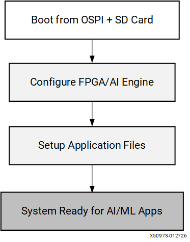
The flow includes three main sections:
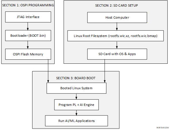
Section 1 (Board Setup): Use JTAG to load and flash the bootloader to the board OSPI memory, then switch the board to boot from OSPI instead of JTAG. If the board already boots from OSPI, skip this section.
Section 2 (SD Card Setup): Flash the Linux root filesystem image to an SD card, then copy the required application files and FPGA overlays to the card.
Section 3 (Board Boot): Boot the system from OSPI and the SD card, then configure the programmable logic (PL) and AI Engine by using the required overlays and application files for AI and machine learning (AI/ML) functionality.
Prerequisites: Host Network Configuration#
The following host network configuration steps are required for the manual setup workflow. Complete these steps before proceeding to Section 1.
Configure a Static IP Address on the Linux Host Machine#
Required for manual setup only. Optional for automated setup.
This guide explains how to copy Linux images to the board by using TFTP and mounting the application on the Linux system running on the board by using NFS. To complete this setup, configure the host machine as a TFTP and NFS server.
Note
Skip this section and the following network service configurations if you are using the automated EOU scripts (OSPI and SD Card Boot Flow). Network services are only needed for manual setup workflows.
Set a static IP address on the host Ethernet interface connected to the board, then run the following commands on the host:
# Obtain the interface name.
sudo ip link show
sudo ifconfig <interface-name> <IP-address> netmask <subnet-mask>

# Example: enxc8a362a6a5be is the interface connected to the board.
sudo ifconfig enxc8a362a6a5be 10.10.70.101 netmask 255.255.255.0
Install the DHCP Server on the Host#
Required for manual setup only. Not needed for automated setup.
The DHCP service handles dynamic IP allocation for the board in the configured subnet. Run the following command on the host:
sudo apt install isc-dhcp-server
Configure the DHCP Server#
Update
/etc/dhcp/dhcpd.confto define the IP address range, router, and DNS servers for the board:default-lease-time 600; max-lease-time 7200; authoritative; subnet 10.10.70.0 netmask 255.255.255.0 { range 10.10.70.1 10.10.70.5; option routers 10.10.70.101; option domain-name-servers 8.8.8.8, 8.8.4.4; }Identify the active interface:
ip link show
Update the network interface in
/etc/default/isc-dhcp-server:INTERFACESv4="<interface-name>" INTERFACESv6="<interface-name>" # Example INTERFACESv4="enxc8a362a6a5be" INTERFACESv6="enxc8a362a6a5be"
Restart and check the DHCP service:
sudo systemctl restart isc-dhcp-server
systemctl status isc-dhcp-server
Configure the TFTP Server#
Required for manual setup only. Not needed for automated setup.
Use the TFTP service to transfer Linux images to the board from the host. The path is set to /home/amd because this is where the release package is extracted. Run the following commands on the host.
Note
Skip this section if you already installed TFTP or if you are using automated EOU scripts.
Confirm that no service uses UDP port 69:
sudo netstat -tuln | grep :69
Install TFTP-HPA:
sudo apt install tftpd-hpa
Edit TFTP-HPA settings in
/etc/default/tftpd-hpa:TFTP_USERNAME="tftp" TFTP_DIRECTORY="/home/amd/boot_images/" TFTP_ADDRESS="10.10.70.101:69" TFTP_OPTIONS="--secure"
Set up the TFTP directory:
sudo useradd -r -s /bin/false tftp
sudo chown -R tftp:tftp /home/amd/boot_images/
Enable and start the TFTP service:
sudo systemctl enable tftpd-hpa
sudo systemctl start tftpd-hpa
sudo systemctl status tftpd-hpa
Configure the NFS Server#
Optional for both setups. Useful for development workflows.
Enable the NFS service only if NFS serves the root filesystem (RootFS) or if you want to transfer files (models, applications) over the network during development. Skip this section if you already installed NFS.
Note
For automated setup users: NFS is optional. The automated scripts copy all required files to the SD card during preparation. However, you can optionally configure NFS for development convenience (for example, quickly copying updated models to the board without re-flashing the SD card).
Install the NFS server package:
sudo apt-get install nfs-kernel-server
Update
/etc/exportswith the shared directory and network access:/home 10.10.0.0/255.255.0.0(rw,sync,no_subtree_check,no_root_squash)
Export the file system:
sudo exportfs -a
Start and enable the NFS service:
sudo systemctl start nfs-kernel-server
sudo systemctl enable nfs-kernel-server
Section 1: Board Setup#
Purpose: Initial Boot and OSPI Programming
Step 1: Initial Board Configuration#
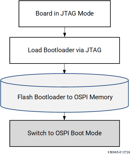
Power OFF & JTAG Mode: Set the board to JTAG boot mode so you can load firmware through the JTAG interface instead of from storage.Use the power slider switch to power off the board, then set the SW1 DIP switch to JTAG boot mode:
SW1 DIP Switch |
Mode Pins [0:3] |
Mode SW1 [1:4] |
|---|---|---|
SDCARD Boot (SD1) |
0111 |
ON, OFF, OFF, OFF |
OSPI / QSPI Boot |
0001 |
ON, ON, ON, OFF |
JTAG Boot |
0000 |
ON, ON, ON, ON |
Step 2: Terminal Setup#
Minicom: Open a serial console to monitor boot messages and interact with the bootloader.
XSDB: Open the Xilinx debugger to communicate with the FPGA and SoC through JTAG.
Open Minicom on the host by using /dev/ttyUSB1 with settings 115200, 8N1.
"sudo apt install minicom"
    “minicom -D /dev/ttyUSB1”
    or
    "sudo apt install screen"
    “screen /dev/ttyUSB1 115200”
On another Host terminal, open JTAG (XSDB):
source <vivado_install_dir>/2025.2/Vitis/settings64.sh
xsdb
Note
Replace ${vivado_install_dir} with your installation directory path.
Step 3: XSDB Commands#
Connect & Load BOOT.bin: This step downloads and executes the bootloader (PDI + U-Boot) directly into the board’s memory through JTAG
30-second process: Flashes the bootloader images to get the board running.
At the XSDB prompt, enter the following commands:
cd /home/amd/boot_images/
connect
set port 3121
target -set -filter {name =~ "*xc2ve3858*"}
dev p BOOT.bin
Note
After you run the command at the XSDB prompt, switch to the Minicom or screen terminal and press Enter when logs appear at the Minicom prompt. The script flashes the PDI and U-Boot images to the board. The process typically takes about 30 seconds.
Note: If you encounter an error during boot, run the following command in XSDB and repeat Step 3.
dev reset
To transfer the OSPI Image using dow, enter the following commands in the xsdb terminal:
dow -data edf-ospi-versal2-vek385-sdt-full.bin 0x20000000
Step 4: Flash OSPI#
sf probe/erase/write: Programs the OSPI flash memory with the bootloader so the board can boot independently the next time.
sf probe 0 0 0
sf erase 0x0 0x10000000
sf write 0x20000000 0x0 0x10000000
Step 5: Switch to OSPI Boot Mode#
Change DIP switch: Configure the board to boot from the OSPI flash that you just programmed instead of from JTAG.
Power off the board.
Set the boot mode to OSPI by toggling the SW1 DIP switch on the board.
Set the OSPI or QSPI boot mode to 0001 (ON, ON, ON, OFF).
Section 2: SD Card Setup#
Purpose: Prepare Linux kernel image and Root Filesystem
Step 1: Prepare SD Card#
Remove and connect: Prepare the SD card for writing on the host system.
Remove the SD card from the target board and insert it into an SD card reader.
Connect the SD card reader to the Ubuntu host machine.
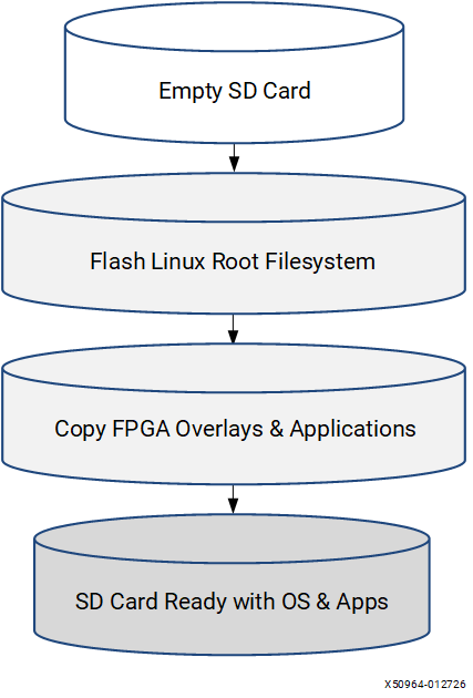
Step 2: Flash root filesystem#
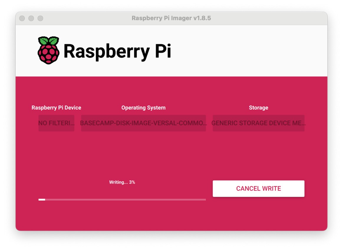
RPi Imager or bmaptool: Write the Linux root filesystem image to the SD card.
rootfs.wic.xz: Contains the Linux operating system, prebuilt machine learning applications, and the required file structure.
Flash rootfs.wic.xz to the SD card by using either method.
GUI method:
Install and start RPi Imager:
sudo apt install rpi-imager
sudo rpi-imager
Configure the settings in RPi Imager:
Raspberry Pi Device: Choose No filtering
Operating System: /home/amd/boot_images/rootfs.wic.xz
Storage: Select the SD card
CLI Method: Use bmaptool on host machine:
sudo apt install bmap-tools
# Identify the SD card device path
lsblk
# NOTE: both rootfs.wic.xz and rootfs.wic.bmap should be in the same path
# Before proceeding, ensure the disk partitions are unmounted using
sudo umount /dev/sdc

# Copy the image to the SD card
sudo bmaptool copy rootfs.wic.xz /dev/sdc
Step 3: SD Card Layout and Partition Activation#
Resize partitions: Expands filesystem to use full SD card capacity (if >8 GB)
SD Card Partition Layout#
In the previous step, flashing the rootfs.wic.xz image writes the complete Linux operating system, prebuilt machine learning applications, and file system structure to the SD card. By default, this process creates multiple partitions on the SD card.
For a 32 GB SD card, the default partition layout after flashing the WIC image appears as follows (example output):
lsblk /dev/sdb

NAME MAJ:MIN RM SIZE RO TYPE MOUNTPOINT
sdb 8:16 1 29.7G 0 disk
sdb1 8:17 1 1G 0 part /media/BOOT # Boot partition (FAT32) - bootloader/kernel
sdb2 8:18 1 1G 0 part /media/rootfs #
sdb3 8:19 1 6G 0 part /media/rootfs # Root filesystem (ext4) - minimal size from WIC
After flashing, the root filesystem partition provides about 6 GB of space, and the remaining SD card capacity (about 21 GB) remains unallocated. To use this additional space on the target, resize the SD card partitions and activate the additional partition from the host machine.
If the root filesystem partition does not provide enough space to copy applications or models, use the unallocated space for models and application data:
Create a second partition on the SD card.
Activate the second partition on the target.
Note
Each time you flash the WIC image to the SD card, repeat the partition resize and activation procedure.
As an alternative, access applications and models over NFS when the host connects to the target. However, NFS access can run significantly slower and might not fit all use cases, especially when large model files or high I/O demands apply.
For step-by-step instructions to resize and activate the additional SD card space, see SD Card Resizing Procedure.
Step 4: Copy Files to SD card#
Copy overlays: Copies PL/AIE configuration files and applications to the SD card
Now copy the required overlays applications to the SD card(/storage).
Mount the partition and copy files:
# create mount point
sudo mkdir /mnt/sdcard

# mount the SD card partition (e.g., /dev/sda4)
sudo mount /dev/sd** /mnt/sdcard

# copy overlays and applications to the SD card
sudo cp -r /home/amd/boot_images/overlay /mnt/sdcard/
sudo cp -r <path_to_models> /mnt/sdcard/

# unmount the SD card after copying
sudo umount /mnt/sdcard
Eject the SD card from the host system using below command:
sudo eject /dev/sd*
Section 3: Board Boot#
Purpose: Final System Configuration
Step 1: Boot the Board#
OSPI Boot: Board now boots from OSPI flash (bootloader) and SD card (filesystem)
Login: Access the running Linux system
Insert the SD card into the board.
Power ON the board
After the board boots successfully, log in as the amd-edf user
Step 2: Copy Overlays#
Transfer files: Copy overlay files (PL and AI Engine PDI files, and the device tree blob) and applications to the running target system.
Copy the required overlays and applications from the SD card to the target board. As an alternative, copy the files from the host machine by using NFS.
If you choose to copy overlays after the target boots by using NFS, mount a host NFS export on the target and copy the files locally.
On the target, mount the host NFS export:
sudo mount -t nfs 10.10.70.101:/exports/root /mnt
Copy the overlay files into the target overlay directory:
sudo mkdir -p /overlay
sudo cp -r /mnt/overlay/* /overlay/
Alternatively, use scp from the host to the target (replace TARGET_IP with the board’s IP):
scp -r /path/on/host/overlay amd-edf@TARGET_IP:/overlay/
Step 3: Program PL + AIE Overlay#
fpgautil: Configures the FPGA fabric (PL) and AI Engine (AIE) with specific functionality.
Mandatory step: Required before running AI/ML applications.
Program PL + AIE overlay pdi and dtb:
sudo fpgautil -b ./overlay/x_plus_ml.pdi -o ./overlay/x_plus_ml.dtbo
Note
This is a mandatory step to program the AIE overlays before running the XRT host application.
Use ‘sudo fpgautil -R -n’ full to remove the overlays and re-program them using the earlier fpgautil command.
Step 4: Copy Configuration Files#
Application configs: Places configuration files where applications expect to find them.
xclbin: Metadata file used by XRT for running AI/ML acceleration applications.
Copy the pre-processing cfg and xclbin into the required folder:
sudo mkdir -p /run/media/mmcblk0p1/
sudo cp overlay/image_processing.cfg /run/media/mmcblk0p1/
sudo cp overlay/x_plus_ml.xclbin /run/media/mmcblk0p1/
This step configures a complete embedded Linux system with FPGA acceleration capabilities. After completion, you can run inference on the board by running the application. The application can be either a Python script or a C++ program. Also, you should copy the Vitis AI compilation output, which is the model cache directory.
SD Card Resizing Procedure#
Purpose: Resize the SD card partitioning so that the remaining free space on the SD card is usable, and (optionally) prepare an additional partition for storing models and applications.
This is an optional step. You can alternatively use NFS to access the applications from host machines. After flashing the rootfs.wic.xz image to the SD card, it occupies about 11 GB of space. To use the remaining free space, expand the storage partition using the following steps on the host machine:
Unmount All SD Card Partitions
# List the SD card device
lsblk

# Umount by SD card device path as obtained above: sda, sdb or sdc, etc.
sudo umount /dev/sdc2
sudo umount /dev/sdc3
sudo umount /dev/sdc4
If you get a “target is busy” error, make sure no applications or terminal windows are using files on the SD card.
Repartitioning with fdisk
#1. start fdisk
sudo fdisk /dev/sdc

#2. Print the current partition table and note the Start value for the VFAT partition (for example, /dev/sdc4). You reuse this exact starting sector:
Command (m for help): p

#3. Delete the last VFAT partition (sdc4)
Command (m for help): d
Partition number (1-4, default 4): 4
#4. Create a new partition using the same starting sector, but extend it to the end of the card:
  •     Press n and Enter to create a new partition.
  •     Partition number: Enter 4.
  •     First sector: This is the most important step. Enter the exact starting sector you wrote down earlier for /dev/sdc4
  •     Last sector: Press Enter to accept the default, which uses all the remaining free space on the card.
  •     Do you want to remove the signature? No
#5. Set the partition type to Microsoft basic data (FAT32 for GPT disks):

Recommended (alias):
        Command (m for help): t
        Partition number (1-4, default 4): 4
        Partition type or alias (type L to list all): Microsoft basic data

Alternative (explicit GUID for GPT):
        Partition type or alias: EBD0A0A2-B9E5-4433-87C0-68B6B72699C7

Note on partition type codes:

  - MBR uses 1-byte codes like 0x0c (FAT32 with LBA).
  - GPT uses 16-byte GUIDs. The correct GUID for a FAT32 data partition is EBD0A0A2-B9E5-4433-87C0-68B6B72699C7, which fdisk also exposes via the “Microsoft basic data” alias.
  - On GPT disks, do not use MBR codes like 0x0c; use the GUID or its alias.

#6. Review and write changes
Command (m for help): w
Resize the Filesystem
#1. Inform the kernel of partition changes (or reinsert the SD card):
sudo partprobe /dev/sdc

#2. Reformat to ensure the filesystem uses the entire partition
# Unmount if still mounted
sudo umount /dev/sdc4
# Format the partition as FAT32
sudo mkfs.vfat -F 32 /dev/sdc4
Verify the Result
The output should now show /dev/sdc4 with its new, expanded size.
lsblk /dev/sdc
Eject the SD card from the host system using below command:
sudo eject /dev/sdc
Insert the SD card and boot from OSPI + SD
Reinsert the SD card into the VEK385 board.
Set SW1 to OSPI boot mode.
Power on the board. The bootloader runs from OSPI and the system uses the SD card for the root filesystem.
Log in to Linux on the target.
Identify the SD card device and its partitions:
lsblk
To automount a partition (for example, /dev/sda4 identified with lsblk) at boot, add an entry to /etc/fstab. This file defines what to mount and where during boot. To grant the non-root user amd-edf read, write, and execute permissions on the VFAT partition, you need to add specific mount options to the /etc/fstab entry. These options tell the kernel which User ID (uid) and Group ID (gid) should “own” all files on the partition and what permissions (umask) should be applied. Here are the steps and the correct fstab entry:
- Find the User ID (UID) of amd-edf
First, you need the numerical User ID (UID) for the amd-edf user. Run this command as a regular user or root:
id -u amd-edf
id -g amd-edf
- Assume this command returns the UID 1000 (a common default for the first non-root user).
Open the file for editing:
sudo vim /etc/fstab
Change the line to:
/dev/sda4 /storage vfat defaults,nofail,uid=1000,gid=1000,umask=000 0 2

What the options mean:
vfat: The partition is FAT32, convenient for sharing data with Windows.
defaults: Standard mount options (rw, suid, dev, exec, auto, nouser, async).
nofail: If the device is missing or the mount fails, boot continues normally.
0 2: Skip dump; run fsck after the root filesystem.
Note
Replace 1000 with the actual UID and GID of the amd-edf user if it is different. The /storage partition is now owned by amd-edf, and that user can read, write, and execute files on it without needing sudo.
The /storage partition is now owned by amd-edf, and that user can read, write, and execute files on it without needing sudo.
ls -ld /storage
Create the mount point:
# create storage directory
sudo mkdir /storage

# Test the configuration without rebooting
sudo mount -a

# Verify the mount:
lsblk
findmnt /storage
After this step, the system mounts /dev/sda4 at /storage during boot. The /storage partition uses the VFAT file system, so both Windows and Linux can access it. Use this partition to copy or download models and other data.